jetZILLA TM quasi-monthly magazine
The family-friendly online magazine of MINIATURE JET PROPULSION!
- March 2003 - Volume 1 Number 2 -

YOU could save
a child's life! >>>

Gary Robinson's second Lockwood engine photo (c) 2002 Outwest-jets
MIGHTY  ROAR  FROM  THE  LAND  DOWN  UNDER
Australian Gary Robinson's second Lockwood valveless pulsejet engine going full blast. This is a good-sized engine -- it is mounted to a full-size racing go-kart frame! Exhaust blast can be seen from the tailpipe (the long cone above the combustion chamber) AND the intake duct (at right end of the chamber in this picture - note how the duct stays cool due to the breathing in of outside air between explosion cycles). [Gary's story of building his first Lockwood and lots more photos appear in this month's Feature Article, below.]

Photo Copyright 2002 Outwestjets

______________________________________________________________
 
jetZILLA   M A R C H   2 0  0 3   E D I T I O N  -
______________________________________________________________

jetZILLA Online Magazine of Amateur Jet Propulsion Development
    © 2003 Cottrill Cyclodyne Corporation
       [a free subscription e-magazine]
Issue 2003-0324-0102-00                       March 24, 2003
Approx. circulation: Unknown
Publisher:  Larry Cottrill, Cottrill Cyclodyne Corporation, 
                Mingo, Iowa  USA   50168-9500
                email: jetZILLA@cottrillcyclodyne.com
[Subscribe / Unsubscribe / Change / Contact information is 
            shown at the bottom of this issue]

Our Subscriber lists are NEVER SOLD to advertisers or any
   other parties. We do not send any unrelated mailings to
   subscribers from this list. We unconditionally guarantee 
   that your name and email address are secure with us!
______________________________________________________________
 
Welcome, everyone!

I N   T H I S   I S S U E . . .
______________________________________________________________
 
1. FEATURE ARTICLE ...
   Roar from 'The Land Down Under' - how I built 
   my first Lockwood valveless pulsejet
   by Gary Robinson

2. VERY SPECIAL OFFER! From a friend of jetZILLA ...
   Get Your Copy of Original Lockwood Research Paper 
   - a 'must have' for valveless pulsejet hobbyists!
   offer by Ben Brockert

3. FROM THE MONSTERS GALLERY ...
   The 'Reynstodyne Shark' tiny valveless pulsejet design 
   by Larry Cottrill

4. PRODUCTS AND STUFF ...
   Products, links, ads, etc...

5. COMING IN THE NEXT REGULAR EDITION ...
   > I Just Don't Know,
     I Just Don't Know ...

6. ALL THAT BOILERPLATE ...
   Who we are, Subscribe, Unsubscribe, Privacy, etc...

_________________________________________________________

 F E A T U R E   A R T I C L E . . .
_________________________________________________________
Next   Contents   Top   Subscribe Now

Roar from 'The Land Down Under' - how I built 
   my first Lockwood valveless pulsejet
   by Gary Robinson
_____________________________________________________

Note from the Editor:

When I first asked for pulsejet articles to print in my new
jetZILLA magazine, a young man from Australia by the
name of Gary Robinson was among the first to respond. Gary 
is a homebuilder of Lockwood valveless pulsejet engines, 
having achieved some success with experimental models in a 
couple of different sizes.

Gary's engines are a lot bigger than what I would advocate
most people (and certainly beginners) building as a hobby, and 
they require a fair amount of skill and tooling for metalworking, 
although absolutely no real machining is needed -- basically, 
just good old-fashioned sheet-metal work, blacksmithing and 
welding. Apparently, he generally uses ordinary mild steel for
his experimental engine work (though he mentions trying out
stainless early on).

I wish I could be there sometime to see Gary's engines running 
in all their glory. Enjoy!  - Larry Cottrill
_____________________________________________________

Why a Lockwood?

I initially built a small valved pulse jet using shim steel as 
reed valve  material. It didn’t take long for me to become 
frustrated with the resulting valve sealing problems. Neither 
my friend Iain Gibson or myself could locate suitable materials 
here in Australia. I had two choices, import some cr2095 [a type 
of spring steel] or similar material, or build a valveless. 

The ‘Chinese’ valveless pulsejet was an obvious starting point 
for a novice. I made it from 0.6 mm S/S [.024 in thick stainless 
steel] sheet salvaged from the rotary drum of a junk clothes 
dryer. Forming the sections was easy but welding the thin 
brittle metal was a headache. 

The Chinese was really a lot smaller than what I really wanted, 
though. Looking for something with a bit more punch, I started to 
think about building a Lockwood [often called Lockwood-Hiller] 
design.

Gary's first Lockwood engine in action - photo by Gary Robinson VIEW LARGE
IMAGE
 
AN EARLY RUN of ENGINE NO. 1 Gary's first Lockwood engine, as described in this article. Exhaust flame can just barely be seen at top left. The black tube below the exhaust cone is the intake duct, where flame is also ejected [though it doesn't show in this run]. Note the curved reflector 'heat shield' just in front of the tailpipe U-bend - this would presumably prevent the kart driver's hair spray from igniting. [The driver's seat seems to be removed in this shot - a little of the 'welded chain' steering wheel (white) is just visible at the right edge] Photo by Gary Robinson - Copyright 2002 Outwestjets Construction This engine was quite easy to fabricate. I used 0.9mm [.035 inch thick] CRS (cold rolled steel) for the short intake nozzle, combustor zone and tailpipe cone. The U-bend is a section of 3 inch [76 mm diameter] mandrel-bent exhaust tubing with an approximately 1.6 mm [.063 in] wall thickness. [Editor’s note: The U-bend is needed in the Lockwood design because a large amount of thrust is developed in the short intake pipe – about 40% of the total engine thrust! The U-bend allows the ‘intake’ and ‘exhaust pipe’ thrusts to work together – if the engine were left straight, the two thrust flows would OPPOSE each other, with a resulting net thrust of only 20% of the total power available! (60% - 40% = 20%) – Ed.] With the help of a cone sheet calculator program that printed the flat sheet layouts (projections), marking out each part was simple. The parts were then cut out using an air powered metal nibbler which handled the 0.9 mm [.035 in] steel sheet easily. The individual parts were rolled in a small hand operated roller, (you don’t really need a slip roll, it is a bonus though). The front and rear transition cones were simply hand formed. Each part had the seam tack welded with a gasless MIG welder before the final welding with oxy/acetylene with a number 8 tip and black [mild steel] filler wire. This was easy though time consuming.
First run of Gary's second Lockwood engine - photo by Gary Robinson VIEW LARGE
IMAGE
 
FIRST RUN OF NO. 2! Gary's second Lockwood engine had several small improvements over the first model, although construction was basically the same. Here, flame from both exhaust and intake are clearly visible. This is a beautiful run - the straight, blue flame is indicative of good, "lean" combustion. Photo by Gary Robinson - Copyright 2002 Outwestjets I used an NGK brand long reach spark plug that has a 10 x 1mm pitch thread. I drilled an 11 or 12 mm hole in the centre of the combustor chamber. Then a 10 x 1mm nut was welded over the outside of the hole. I ran a bolt through the nut to locate it during welding (the bolt should be oiled or coated with ‘Never Seize’ compound so it is easier to remove after the heat produced during welding; the bolt through the centre also serves to eliminate warpage during welding and protects the internal threads of the nut from weld spatter). My fuel injector is nice and simple too. A brass fitting that accepts 3/8" hose and has a 1/4 npt male thread is drilled out to take a short straight length of 5/16" steel brake line. The steel and brass are silver soldered together. [Amazingly, the silver solder (silver braze) does not melt despite the awesome heat of the running engine - the rapid dispersal of LPG [another name for Propane -Ed.] through it keeps it cool.] Then a 1/4 NPT (national pipe thread) female socket (hose joiner type) purchased from an auto or hydraulics shop (cut in half so you get two fittings for the price of one) is welded in the appropriate spot, after drilling a hole of course, same basic procedure as the spark plug mount, except no bolt through the guts of it during welding. Assembly was finally completed!
Another view of engine no. 2 running full-bore - photo by Gary Robinson VIEW LARGE
IMAGE
 
LOOK, MA - NO MOVING PARTS! Mechanically speaking, valveless pulsejets are the simplest internal-combustion engines ever - not even a reed valve to block explosion gases from leaving through the intake! In the Lockwood, there are no internal structures whatsoever [not even the flameholders found in ramjets]. There is also no fine machining required -- just sheet metal cutting, rolling and welding. Simplicity itself [but, how DOES Gary make that wonderful U-bend?]. Photo by Gary Robinson - Copyright 2002 Outwestjets Final preparations & my ‘test bench’ To tap fuel from the LPG bottle, I used an older type gas regulator (think ‘BBQ’ here) that has a screw-on (removable) fitting which mates with the gas bottle - the other end is generally a 1/4 NPT male thread. Onto that male thread is screwed a 1/2" 90-degree on/off ball valve tap which is fitted with a brass hose tail that takes 3/8" common black rubber, nylon braided fuel hose. This handles the job well if handled carefully [proper cutting, fitting and clamping of hose, using exactly the right fittings, keeping hose safe from accidental damage, replacing hose when needed as it ages, etc. – Ed.]. Double hose clamps on all fittings are a must, as is LPG grade thread tape on fittings. (It is thicker than standard water pipe thread tape). 1-1/2 times around the fitting is the rule for this type of tape. I have also found Loctite liquid pipe thread sealant works well with gas. The left-hand thread gas-bottle-to-1/4 NPT fitting can be bought at all good hardware stores, too. I thought of making a small wheeled trolley to allow me to measure the thrust using a large dial faced spring scale but was lucky enough to happen upon a very second hand racing go-kart which set me back approx $50 US. A simple frame was added to allow the ‘Locky’ to be easily fitted or removed by three ordinary exhaust pipe clamps. Using about $3 US worth of electronic components, my brother Douglas built a trigger unit which was connected to a Firefly transistorized ignition and a GT40 coil that were hanging around the shed at the time. This was all powered by a small gel cell glider battery. He allowed for the spark to be variable in frequency as well. This unit throws a good 3/4 inch long spark very reliably. Ready to start !?!
Another view of engine no. 2 running full-bore - photo by Gary Robinson VIEW LARGE
IMAGE
 
ON THE SHOP FLOOR Gary's Lockwood no. 1 rests peacefully 'upside down' in the foreground, while monster no. 2 [bolted to the kart frame] is 'in the works' in this shot. No. 2 features a removable tailpipe cone which adds experimental flexibility at the cost of a little added complexity. Gary, that shiny new sheet metal really looks an awful lot like stainless! Photo by Gary Robinson - Copyright 2002 Outwestjets First run The first thing I noticed was the absence of an instruction manual! No worries, though - being what my wife calls a "typical male", I most probably would have tossed the instructions aside until all else failed, anyway. My brother Douglas was again present, to assist me on the maiden start-up. We placed the go-cart about 1 metre away from the shed [what we in the US call our 'garage' -Ed.], aimed straight for the shed wall, just in case. Gas bottle and spark box were both quickly connected, and gas connections double-checked. After a few pops and bangs I managed to catch the engine on just the right stroke and it began humming gently, as a big gas burner might do. No flames licked from either pipe but were fully contained in the combustor area. It did seem a little quieter than I expected, though. Douglas pushed the cart backwards 2 feet and it slowly rolled forward. After this happened several times I began to wonder if I had expected too much out of this engine. He pushed the cart back once more and I opened the gas tap full on and gave the engine a squirt of compressed air in the short intake at the same time. INSTANTLY, the engine roared to life; in a fraction of a second the kart catapulted forward, knocking Douglas over and using his body as a ramp to climb the shed wall as he was falling backwards! Stunned by the suddenness of all this, I hurled myself towards the dragging gas bottle to shut it off. Truth is, we then laughed so hard we had to wait for the tears to subside before we could go for a cold beer and relate it all to the curious townsfolk. Success at last!
Gary's 'linear mini Lockwood' - photo by Gary Robinson VIEW LARGE
IMAGE
 
LITTLE "LINEAR" LOCKWOOD [ say that five times fast! ] Gary also produced a small version of the Lockwood engine, without the U-bend! This doesn't give you much thrust for propulsion, but still delivers plenty of heat and noise. [It could easily be bent into the conventional Lockwood form, if desired, of course.] Gary's obviously happy with the way this little beast is 'purring'! Note his use of hearing protection -- vital when working up close to any pulsejet! Photo by Gary Robinson - Copyright 2002 Outwestjets Measured performance The cart pulled 55 lb on the scale on its first run before the conical tail pipe imploded. [Editor’s note: ‘Imploded’ does not mean anything violent in this case. There is often a slightly lowered static pressure developed in a pulsejet tailpipe. Once Gary’s Locky got sufficiently red hot from running, the cone was soft enough that this low pressure caused it to pull inward and collapse, ruining further running of the engine – a disagreeable but not dangerous condition.] After making a new tailpipe cone out of 1.6 mm [.063 in] sheet steel and doing some tweaking of the fuel injector, it pulled close to 70 lb! [Editor’s note: People often ask about the ‘horsepower’ of our pulsejets. Properly expressing the power developed by any type of jet engine is not simple, and it changes significantly with forward operating speed. The aviation powerplant industry actually has several different methods of defining and calculating power. The method I always use for approximating pulsejet power is to multiply pounds of static thrust (thrust at 0 forward speed) by the factor .59 – this is supposed to give the equivalent horsepower of a piston engine driving a propeller of reasonable efficiency. On that basis, the two thrust figures Gary mentions above would yield the following HP equivalents: 55 lb x .59 = 32.5 HP, approximately 70 lb x .59 = 41.3 HP, approximately Many aerospace design engineers would argue the need for more precise methods, but this approximation is at least simple and direct – in practice, 60% is close enough, and makes a rough estimate usually achievable without pencil and paper. This has always seemed to me to be a reasonable comparison, since jet engines are basically ‘air movers’, as is an engine-driven propeller. Note that this factor is only good for STATIC thrust comparisons; a standard propeller always LOSES efficiency as forward speed increases, while most jet engines GAIN efficiency with speed, up to a point. – Ed.] More [and future] Lockwoods
Jessica Robinson holding the 'linear mini Lockwood' - photo by Gary Robinson VIEW LARGE
IMAGE
 
SUPERGIRL HEFTS MIGHTY MINI Gary's daughter Jessica demonstrates the Incredible Lightness of Valveless Pulsejets by hoisting the straight mini Lockwood. In the background is the full-sized bent version, mounted behind the driver's seat of Dad's 'go-kart test bench'. ['Valvoline' would not be used in any pulsejet, unless you just want to experiment with burning it as (rather expensive) fuel!] The engine being lifted is the same one shown running in the previous photo. Photo Copyright 2002 Outwestjets The small ‘linear’ [un-bent] Lockwood shown in the picture above, held by my daughter Jessica, was an attempt at scaling down the 5.25" exhaust diameter Lockwood. It is just over a metre [3.28 ft] long and has a terminal exhaust size of 1.75" [about 45 mm] diameter. It starts quick and runs loud. The noise level would be similar to a 6 cylinder engine with no exhaust running at about 4,500 rpm no load (comparing to my old speedway car here). In the future I hope to build a ‘Maxi Lockwood’ with an 8.75 inch [that's 222 mm!!! -Ed.] terminal exhaust opening, and a still smaller ‘Micro Lockwood’. - Gary Robinson _____________________________________________________ Photo Credits: All photos in this article were provided by, and are property of, the author. _____________________________________________________ Gary Robinson is a pulsejet designer, builder and experimenter living somewhere in Australia. To contact him about this article, email: lattice@hwy.com.au _____________________________________________________

_________________________________________________________

 -   V E R Y   S P E C I A L   O F F E R   -

 F R O M   A   F R I E N D   O F  jetZILLA  . . .
_________________________________________________________
Next   Contents   Top   Subscribe Now
Get Your Copy of the Original Lockwood Research Paper
   - a 'must have' for valveless pulsejet builders!
offer by Ben Brockert, pulsejet hobbyist
_____________________________________________________

Note from the Editor:

I just got this from friend and fellow enthusiast Ben Brockert. He has
discovered an early copy of the original paper on the Lockwood design, 
prepared for Hiller Aircraft by Ray Lockwood, who was employed by 
Hiller in the 1960s, and is making new copies available to any pulsejet
hobbyist who wants one. I have obtained my copy from Ben, and it is a 
wonderful paper, not overly mathematical, with an excellent description 
of the theoretical and practical advantages of valveless pulsejet 
designs, and of the Lockwood design in particular. It includes some 
performance related graphs and other research data. For anyone
interested in valveless pulsejet theory, this is an unbelievable bargain
for your two bucks (payable through your PayPal account).

My advice is, DON'T pass this up -- GET YOUR COPY NOW!

Thanks, Ben! I'll bet you'll have more like this for us in the days
ahead -- keep up the great research!

What follows is Ben's note to me announcing this offer. 
 
- Larry Cottrill
_____________________________________________________

To: Larry Cottrill, Editor, JetZilla Magazine
From: Ben Brockert


Hello Larry,

In my continuing search for knowledge from the first era of pulse 
jet research, I recently found a copy of an interesting document. 
Written by R. M. Lockwood in 1964 and entitled "Pulse-Reactor Low 
Cost Lift-Propulsion Systems", it includes the basic theory of 
operation of the Lockwood valveless pulse jet; as well as 
experimental data on augmentation, fuel efficiency, and noise 
reduction.

I'm offering copies of this paper for $2(US)/each, with all proceeds to
be used in future searches for more documents. Details can be found on 
my web site at http://www.hepjet.com/docs/

Larry, thanks for your new contribution to the field,

Ben

_________________________________________________________

 F R O M   T H E   M O N S T E R S   G A L L E R Y . . .
_________________________________________________________
Next   Contents   Top   Subscribe Now
_____________________________________________________

Note from the Editor:

In this feature of each issue, we'll feature one of my own
designs from our Gallery of Hopeful Monsters. These
will generally be jet engines or related equipment that are
PROPOSED designs that are as yet untested and unproven --
BUILD AT YOUR OWN RISK !!! No full-size plans, scale prints
or detail drawings, other than what we show here, are available.
Also, since these are usually just proposed designs that we haven't
even built ourselves, we offer almost no technical information --
these are definitely for advanced experimenters who are used to 
working out the fine points on their own!

So, these designs are mostly presented to give you something to
think about, although advanced hobbyists can try to build them
and get them to run. Let us know if you have any amazing
successes to report!

One of my latest designs is the Reynstodyne(TM) Shark(TM) engine, so
called because of the rearward-sloping 'fin' intake. In this case,
the prototype actually has been built [as shown in the photos
below, with comments], but preliminary testing has not been very
conclusive [testing was cut short because my starting air 
compressor bombed -- I now have a replacement, but it's been too 
cold and wintery for the last couple of weeks to stand around 
outside for testing].

A final note is that my friend Ben Brockert suggested lengthening
the tailpipe so it would be somewhat MORE than twice the length
of the front chamber. This opinion was based on his reading of the
great work of F. H. Reynst. I took his advice, not by lengthening the
tailpipe, but by shortening the chamber approximately 3/4 inch (18mm)
thus moving in the direction of being more compact, rather than 
significantly longer. One of these days, it's going to warm up a little,
and then I'll find out what we've got here! 

Stay tuned ...  - Larry Cottrill
_____________________________________________________


The ReynstodyneTM 'Shark' tiny valveless pulsejet design 
   by Larry Cottrill
Copyright 2003 Larry Cottrill

Basic design & dimensions drawing of Reynstodyne 'Shark' engine (c) 2003 Larry Cottrill VIEW LARGE
IMAGE
 
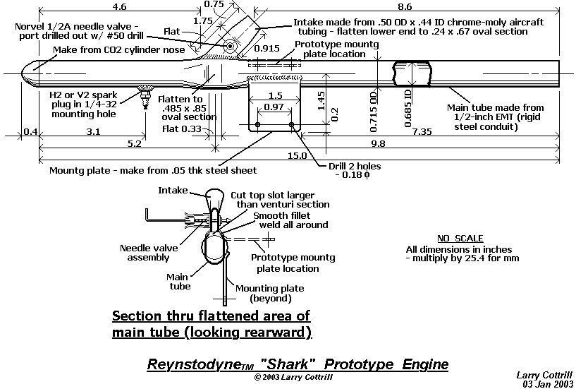
REYNSTODYNETM 'SHARK' ENGINE The original shark prototype drawing, as disclosed on 03 January 2003. In a recent modification, the length of the ignition chamber has been reduced by taking out .75 inch in front of the spark plug. Drawing Copyright 2003 Cottrill Cyclodyne Corporation Original disclosure 01/03/2003 on Kenneth Moller's Valveless Pulsejet Forum, as follows: [ Well, here's the latest -- the Reynstodyne(TM) 'Shark'(TM) prototype engine: The drawing should be self-explanatory, but a couple of details bear a bit more explanation: The idea of the 'sharkfin' intake is that the easiest path provided for entering air will be forward into the chamber. This does not mean that significant air won't be diverted rearward to fill in the tailpipe behind the hot gas 'piston' as it exits. The way you attach the intake venturi to the pipe is important. You cut the slot in the top of the pipe MUCH larger than the cut off base of the flattened tube venturi (so the venturi would actually fall down in!). Then, you clamp the intake in place 'hovering' over the slot and tack weld in a couple of spots by 'bridging' across the gap, then bend it around the tack welds a little til it's lined up true with the tube centerline. Then, tack weld in a couple more spots, and finish weld all around, again 'bridging' your weld across the gap. What you end up with is a fairly smooth flow transition on the inside where it counts. That sounds a lot trickier than it is -- the gap is only a sixteenth of an inch or so, all around. It took about 20 minutes to do the whole job. You make the intakes two at a time by flattening the middle of a short piece of tubing to the 'just right' width, and then cut diagonally across the flat with the jeweler's saw. Then, drill through for the needle valve -- simplicity itself. The drawing shows the mounting plate as it would be on a production engine (fin to the top) -- for testing purposes, I placed it on mine so the fin would be on the left side and the plug on the right. That's why there are those 'ghost images' of the mount in the 'prototype location'. Location and orientation of this plate should be completely non-critical, except that I wouldn't put it up front on the chamber somewhere because of its potential for heavy heat conduction. My insistence on having the sparkplug where the incoming carbureted air/fuel stream washes over it may not be optimal -- it's just located that way because I thought it would make for easy starting. Once the engine's running, the plug should mean nothing, of course. I did not include a football filler type air pipe aimed across the needle valve and down the throat, though I may end up needing to add one. I decided that I'd try starting the Shark either by blowing air in with a hand-held miniature nozzle, or try just spraying fuel in from a pressure can, via a tiny tube extended down through the intake throat! Based on my earlier experimentation, the needle valve will probably need to be way open (5 or 6 full turns) for good starting. ] Recent design/change notes on this design: - Current prototype has had the front chamber reduced in length by .75 inch (18mm) from the drawing dimensions shown, to make certain the chamber length is LESS THAN 1/2 the tailpipe length [ref: F. H. Reynst] - It is probable that location of the sparkplug in the bottom of the chamber is not good design, since it makes the plug potentially susceptible to fuel flooding during starting; side location is probably better - 'Football filler' starting air pipe was added to the intake to aim starting air properly across the fuel port of the needle valve assembly; this resulted in more reliable ignition during starting attempts 
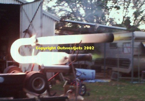
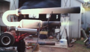
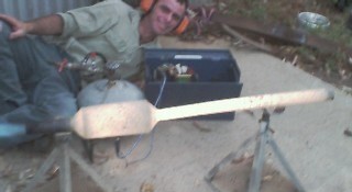
Prototype Engine Photos:
Reynstodyne 'Shark' engine next to tape rule to show size (c) 2003 Larry Cottrill VIEW LARGE
IMAGES
 
VIEW LARGE
IMAGES
 
Reynstodyne 'Shark' engine next to tape rule to show size (c) 2003 Larry Cottrill
A COMPACT VALVELESS PULSEJET DESIGN These shots show the completed SharkTM prototype engine, laid out by a tape rule (inches) - original overall length as shown here was just over 15 inches [.4 m]. It has since been reduced by .75 inch [18mm]. In the upper photo, the engine is shown mounted on the test frame, with fuel tank [just behind engine tube] connected to the needle valve body. Photos Copyright 2003 Cottrill Cyclodyne Corporation
Reynstodyne 'Shark' engine seen up close from the nose end (c) 2003 Larry Cottrill VIEW LARGE
IMAGES
 
VIEW LARGE
IMAGES
 
Reynstodyne 'Shark' engine seen up close from the tail end (c) 2003 Larry Cottrill
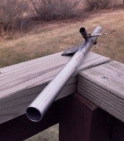
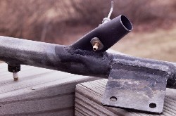
THE SHARKTM IN PERSPECTIVE The engine seen from the nose end [upper photo] and exhaust end [lower photo]. Note the spark plug ahead of and opposite to the 'shark fin' intake tube. In the lower shot, the rim of the rearward-facing intake opening is visible above the needle valve assembly. Photos Copyright 2003 Cottrill Cyclodyne Corporation
Reynstodyne 'Shark' engine closeup of 'shark fin' intake area (c) 2003 Larry Cottrill VIEW LARGE
IMAGES
 
VIEW LARGE
IMAGES
 
Reynstodyne 'Shark' engine closeup of 'shark fin' intake area (c) 2003 Larry Cottrill
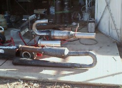
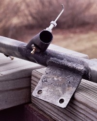
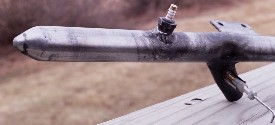
NOZZLE ZONE AND INTAKE TUBE DETAILS These shots show the slightly pinched nozzle area between the ignition chamber and tailpipe, and details of how the flattened area of the intake tube is blended into the main tube in this region. The needle valve body penetrates the intake tube through this narrow section. [An air tube for starting was added later to the lower edge of the intake rim.] Photos Copyright 2003 Cottrill Cyclodyne Corporation
Reynstodyne 'Shark' engine ignition chamber & plug mount (c) 2003 Larry Cottrill VIEW LARGE
IMAGE
 
IGNITION CHAMBER AND PLUG MOUNT DETAIL Inverting the engine allows the plug mount and its relationship to the intake tube to be clearly seen. During starting, the forced draft of fuel/air mixture will cross the tube and flow forward down the side around the end of the spark plug. The plug mount is sufficiently thick that only the spark electrodes of this long-reach plug are allowed to clutter the inside wall of the tube. Photo Copyright 2003 Cottrill Cyclodyne Corporation Theory of Operation The SharkTM is what I refer to as a 'Reynst pattern' engine. What I mean by this is a pulse combustion engine where the ignition chamber is separated from the tailpipe by an air inlet, and where the front of the chamber is closed and all breathing of the chamber to support combustion takes place at its rear opening after expulsion of the explosion product gases. This definition does not necessarily mean that all the air is taken in from the gap [i.e. with none of it coming back in through the tailpipe], but in fact that may actually be the case in such designs. 'Reynst pattern' devices are extremely efficient burners; in fact, F. H. Reynst developed his famous 'Reynst pot' not as a propulsion device but rather as an industrial burner for special heating applications. As such, the 'pot' itself is not optimized for ejected mass at high velocity, but rather for efficiently burning fuel and recovering the combustion energy as heat. However, efficient combustion is one primary concern for a practical jet powerplant. It is hoped that the design shown here will eject mass rapidly enough for good propulsive force [thrust] while retaining a reasonable semblance to Reynst's high efficiency mode of operation. A non-mathematical description of a single operational cycle is as follows:
  • After the fuel/air charge explodes in the front end of the ignition chamber, the extremely sudden pressure rise causes a rapid expansion which compresses the air [or residual exhaust gas] in the rear of the chamber and begins to accelerate this gas mass rearward.
  • As the gas mass accelerates rearward, the portion of gas that started out inside the chamber passes through the relatively narrow nozzle zone, which locally increases its rearward velocity and drops its static pressure. The lowered static pressure prevents the gas from being ejected outward through the intake port, since the outside air is at normal pressure. Thus, beginning at this point in the cycle, the chamber is effectively 'valved off' from the outside air and fuel. For all practical purposes, the exhaust flow is not influenced by the presence of the air intake, and the engine behaves as a continuous pipe closed at one end for this part of the cycle.
  • As combustion within the rear of the moving gas mass continues, the gas slows and regains static pressure as it exits the nozzle zone. Expansion continues to drive the gas rearward, and the 'leading edge' of the gas mass begins to exit through the tail end of the pipe.
  • At some point, practically all the explosion energy has been transferred to the gas mass as rearward momentum [though a significant fraction has been lost as heat to the metal engine shell]. At this point, the gas mass acts as a 'piston' pulling the very low-density residue in the chamber into a condition of 'overexpansion'; that is, the static pressure in the chamber begins to drop.
  • Eventually, the gas mass has moved so far rearward that the overexpanded area occupies the entire chamber and reaches into the nozzle zone and covers the inside face of the intake tube. Because the overexpanded gas has low static pressure, the outside air pressure begins pushing the air in the intake tube inward into the interior of the engine. From this point in the cycle, the chamber is "valved on" to fresh air and fuel! As air flows in, it will be replaced by fresh air from the outside beyond the outer intake rim. The behavior of the engine is now that of a short low-pressure chamber open to standard pressure air via a narrow opening.
  • The whole air column in the intake is now in motion, and flow will continue until the pressures again equalize; this will take a while because of the volume of the chamber. Because the lower zone of the intake pipe is flattened to a much smaller internal cross-section than the outer intake rim, the air is accelerated to a much higher velocity in this region, and the static pressure drops. This means that the liquid fuel present at the fuel port in the needle valve body will be drawn into the airflow, since the fuel external to the valve is at more-or-less outside air pressure. Because of the shear and turbulence effects on the air as it passes around the needle valve body, the fuel drawn in is immediately atomized, so it will be rapidly evaporated into the air stream as it enters the engine.
  • As air/fuel mixture pours in, it is routed by the geometry of the intake pipe, the nozzle and the chamber forward, deeper into the chamber. At the same time, the main gas mass in the tailpipe continues outward, but some of its 'trailing edge' combustion is slowed and eventually pulled forward through the nozzle zone into the chamber. Eventually, the material in the chamber has sufficient density and pressure, and the proper fuel/air ratio to form an explosive mixture that can be ignited.
  • The exhaust gas mass in the tailpipe is also influenced by the pressure difference that has been developed. This pressure difference acts as a force in the forward direction, and the exhaust mass as a whole starts to slow down in response to this force. Whether this mass actually undergoes reversal and begins pouring back into the chamber through the nozzle depends entirely on how long it takes for standard pressure to be regained in the chamber. At any rate, to some extent, the engine now behaves as a short low-pressure chamber open to standard air pressure via a small port and below-standard but increasing pressure gas via a significantly larger opening.
  • The accumulated mixture, reaching approximately the static pressure of the outside air, ignites explosively to begin the next cycle of operation. [It is not perfectly understood whether ignition happens because of the recycled gases pulled back in from the tailpipe or simply because of residual "free radicals" in the chamber. Once the combustion chamber walls attain high temperature, this may also affect the precise instant of ignition. However, the composition, pressure and density of the mixture are probably the biggest determining factors in the precise timing of the explosion.]
  • The complete cycle described above would take approximately 3 milliseconds, with a pulse frequency of about 330 cycles/second, with the engine dimensions shown in the drawing. If you decide to try to build a working model of this experimental design, make sure you get plenty of photos and email them to us in GIF or JPG format to display in a future issue [we will make the final decision as to the best ones to use, and we'll show your name as a photo credit.] And, why not try writing an article about building and firing it? We don't pay for articles, but we'd be glad to help you "get your name in print". Also, any author whose article we accept gets a free ad for your e-business or Web site! Naturally, we will provide editing as needed for publication in readable US English. - Larry Cottrill
    "To God Alone be the Glory"
    - Johann Sebastian Bach 1685 - 1750

    _________________________________________________________
     
    P R O D U C T S   A N D   S T U F F  . . .
    _________________________________________________________
    Next   Contents   Top   Subscribe Now
    
    __________________________________________
     
    V i s i t   O u r   F r i e n d s  . . .
    __________________________________________
    
       Bruce Tharpe Engineering - 8622 E Evans Creek Road, 
          Rogue River, OR 97537  Phone: 541-582-1708. 
          Assembled fuel bladders, pulsejet model plans and 
          MUCH more.   email: tharpe@cdsnet.net
          Site: www.btemodels.com    
    
       ModelFlight - United Kingdom 
          A top-notch magazine for model flyers -- check out 
          the 'Gallery' section for photos of some absolutely 
          beautiful aeromodeling work from all over. Lots of 
          scale stuff. Good construction hints, reviews, etc. 
          All kinds of aeromodeling represented, including the 
          occasional jet craft. www.modelflight.fsnet.co.uk    
    
    ____________________________________________
     
    V i s i t   O u r   O w n   L i n k s  . . .
    ____________________________________________
    
       Tools for Marketers / Webmasters [ TfMW ] -
         Page 2 [ complete product catalog ] - 
          www.cottrillcyclodyne.com/NetProd_page2.html    
    
       Cottrill Cyclodyne SFOATM Pulsejet Engine Design / 
          Development Page - where "Steel Floats On Air"!
          www.cottrillcyclodyne.com/SFOA1.html    
    
       Cottrill Cyclodyne Corporation Site Directory - 
          www.cottrillcyclodyne.com/Page_9999.html    
    
       jetZILLA Initial Press Release [ return to the 
          jetZILLA home page, then select from 'Archived 
          Editions' ] - 
          www.jetzilla.com    
    
    _____________________________________________________
     
    M a k i n g   M o n e y   o n   t h e   'N e t  . . .
    _____________________________________________________
    
       ALL-NEW - Internet Marketing How-To Workshop 
          hosted by Willie Crawford. If You Are a New But  
          SERIOUS Marketer, here's THE one you MUST NOT MISS - 
          Pensacola, FL - May 2-4, 2003 - At just $777, this WILL 
          SELL OUT FAST: Willie Crawford, Tony Blake, Bob Silber, 
          Armand Morin, Gary Knuckles, Ramon Williamson, Fred Gleeck 
          AND Stephen Pierce ALL TOGETHER FOR THE FIRST TIME. This 
          PRICE INCLUDES SIX MONTHS PERSONAL FOLLOW-UP after the 
          workshop ends! On April 15, this goes up to $997 - YOU 
          MUST ACT NOW ...
          Internet Marketing How To Workshop    
     
       Push Button Publishing - 
          Bryan Winters promises: "Not Only Will I Show You
          How to Make Your Living Online, I'll Also Pay For
          the Products, Services, and Resources Needed to 
          do it: Web hosting, Autoresponders, Ad Tracking, 
          and More!" Click here for the solution you've been 
          searching for: www.pushbuttonpublishing.com    
    
    
    _________________________________________________________
     
    C O M I N G   I N   T H E   N E X T   E D I T I O N . . .
    _________________________________________________________
    Next   Contents   Top   Subscribe Now
    
       > I Just Don't Know,
         I Just Don't Know ...
    
    _________________________________________________________
     
    A L L   T H A T   B O I L E R P L A T E . . .
    _________________________________________________________
    Contents   Top   Subscribe Now
    ____________________________________
     
    T h e   W e b   E d i t i o n  . . .
    ____________________________________
     
    If you're reading the email version of this newsletter, 
    you may find the Web version much more enjoyable. It is 
    prettier, and you don't have to click on the pictures to 
    view them! Go to 
    
    http://www.jetZilla.com and click on the 'Current Edition' link. We also provide a link for Web pages archiving past issues. _________________________________________________________ D o n ' t T r y ' R e p l y ' . . . (email version) _________________________________________________________ Like virtually all newsletters/ezines on the 'net today, jetZILLA is mailed via an autoresponder - using your 'Reply' button will just result in 'bounced' (nondeliverable) email. Please use the Subscribe / Unsubscribe / Change / Contact information detailed below. _______________________________________________ W h o I n t h e W o r l d A r e W e ? _______________________________________________
      Larry Cottrill with Reynstodyne(TM) Shark(TM) engine prototype after early test firing - Photo Copyright 2003 Cottrill Cyclodyne Corporation
      Larry Cottrill with ReynstodyneTM SharkTM engine prototype after early test firing
    Photo Copyright 2003 Cottrill Cyclodyne Corporation
    My name is Larry Cottrill. I'm Director of Product Development and Acting CEO of Cottrill Cyclodyne Corporation, registered as a for-profit corporation in the State of Iowa, USA. We are striving to create the world's smallest, safest and most practical hobby jet engines. We also have an intense interest in Internet- and Web-based marketing [since our future products will be promoted and marketed extensively online] and offer top-quality, low-cost and no-cost resources to help make the jobs of marketers and webmasters easier, more cost-effective and more productive. ________________________________ T h i s N e w s l e t t e r a n d Y o u (email version) ________________________________ You are receiving this free issue because of one of the following: -You specifically elected to subscribe from one of our Web pages -I know you personally and thought you'd like it -I asked you if I could send it and you agreed to try it -Online, you recently expressed interest in receiving information related to miniature jet propulsion systems -Someone you know forwarded it to you because they believed you'd enjoy it or benefit from it [see subscription instructions below]. If you don't want to receive future issues, scroll to the bottom for unsubscribe instructions. You are free to unsubscribe at any time in the future, of course. Our goal is a monthly newsletter that will: -help you enjoy the miniature jet engine hobby -share articles and other resources of interest -be easy to read and truly informative -answer specific questions asked by our readers Your email address is the ENTIRE CONTENT of our database listing for you. NO FURTHER DATA IS ON FILE, AND YOUR SUBSCRIBER INFORMATION IS NEVER SHARED IN ANY MANNER FOR ANY PURPOSE. PERIOD. All related mailings from us will ALWAYS be clearly identified with the jetZILLA brand name/trademark. _______________________________________________ F r e q u e n c y o f P u b l i c a t i o n _______________________________________________ Our newsletter is sent/updated approximately once per month, except for RARE instances of non-commercial 'public service' information that we feel is of an urgent nature warranting a 'Special Edition'. ___________________________________________ C o m m e n t s a n d Q u e s t i o n s ___________________________________________ Comments, reader questions and suggestions are always welcome! You are free to contact us at any time: email: Comments@jetzilla.com We will do our best to respond within 48 hours, at most. We reserve the right to publish questions and answers if we think they would be of interest to other readers - if you don't want your name published, please type 'Withhold Name' at the top of your question. We will NEVER publish your email address, unless you include it yourself in a BRIEF 'signature' block beneath your name at the bottom of your email text. ________________________________________________ H o w t o S u b s c r i b e (email version) ________________________________________________ Just use this link for your subscribe request: www.jetzilla.com/jetZilla-subscribe.html and click on one of the links to create a 'subscribe' email. You do not need to fill in the Subject line or include any text. Be sure you do this FROM THE EMAIL ACCOUNT WHERE YOU WANT TO RECEIVE each email issue of jetZILLA ezine. ________________________________________________ H o w to C h a n g e Y o u r S u b s c r i b e r D a t a (email version) ________________________________________________ It's easy to change your subscription data - just use the following procedure: A. Unsubscribe, using the link at the BOTTOM of this email. B. GO TO THE EMAIL ACCOUNT WHERE YOU WANT TO RECEIVE jetZILLA ezine, and use the ‘Subscribe’ link (same as above): www.jetzilla.com/jetZilla-subscribe.html It is not necessary to include text in the body or Subject. ____________________________________________________ H o w t o U n s u b s c r i b e (email version) ____________________________________________________ We're sorry to see you go! But, we realize that people's needs change, and not every publication can be beneficial to every possible subscriber. We hope you've enjoyed being with us and that you've benefited in some way by receiving jetZILLA ezine. Just click on the Unsubscribe link at the bottom of this email. You should receive an acknowledgement email very soon thereafter. Thank you! - Larry Cottrill, publisher jetZILLA ezine

    Page updated: 17 March 2003

    Copyright 2003 Cottrill Cyclodyne Corporation
    - All rights reserved -